


If you’ve ever considered getting a patch bay for your studio, then this is the definitive article for you. Whether your setup is still growing or you already require routing flexibility, your workflow can improve by investing in a patch bay.
A patch bay enables you to quickly connect outboard processors, preamps, converters and virtually any piece of audio gear you have in your setup. And because a patch bay offers you so much flexibility, you can quickly and easily experiment with new and complex routing options that simply would not be possible otherwise.
If you happen to work out of a multi-room facility, you can use patch bays to run tie lines that connect equipment and sources from multiple on-premise locations. A patch bay is also a great investment even if you have a smaller project studio, as it will be easier to integrate new gear like compressors, effects and more.
In this article, we’ll cover some patch bay basics, including connection types and how to plan for your patch bay integration, as well as some tips for routing, wiring and labeling.
If you’re unsure where to begin, you can always contact Guitar Center Professional’s dedicated team of experts for a free, no-obligation consultation.
What Is a Patch Bay?
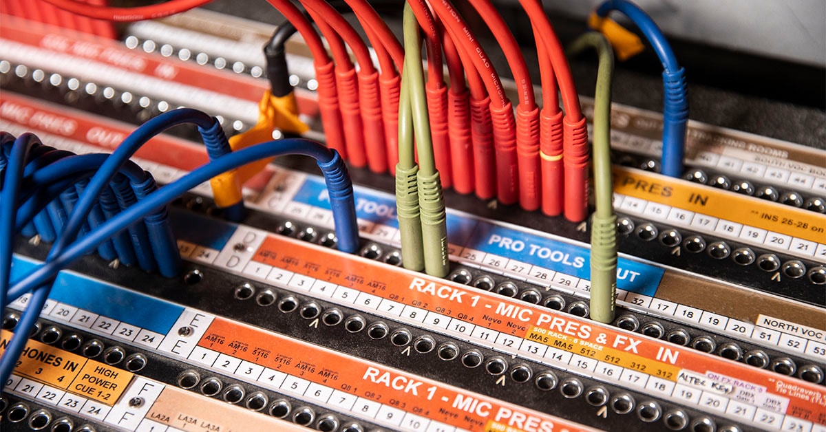
A patch bay is used to connect the inputs and outputs from multiple pieces of outboard gear so that you can route audio signals between them as well as your console. Some patch bays are capable of passing digital audio over copper, like AES, for example. Furthermore, there are specialized patch bays designed for various AV protocols, including video, control and Ethernet networking. There are even software-based virtual patch bays that allow you to route audio between various DAWs, virtual instruments and effects plug-ins without the signal ever leaving the digital domain.
The most common types of professional patch bays include TT/Bantam, TRS, XLR, DB25 and ELCO/EDAC. The two most popular types of patch bays are often configured with either 48 (1/4”) or 96 (TT/Bantam) patch points per rackspace (RU). Patch bays that use XLR or ELCO/EDAC for front-facing connections usually offer fewer patch points due to the space required for those larger connectors.
You may also come across a type of patch bay often referred to as a recording studio cable passthrough panel. These come in a variety of configurations, including TRS passthrough and XLR passthrough.
Popular Studio Patch Bays
Switchcraft StudioPatch 6425 64-Point TT to DB25 Patch Bay
The StudioPatch 6425 is an ideal solution for studios that need to connect both analog and digital signals. With 64 front-facing TT/Bantam jacks and rear DB-25 connectors, the StudioPatch 6245 offers the flexibility you’ll need to connect all your gear and features user-configurable normaling positions on every set of its 32 channels.
Bittree Patch Bays
Bittree offers a number of high-quality professional patch bays, including several 96-point TT to DB25 solutions, in addition to half-rack options like the PS48DB25F, a 48-point TT to DB25 patch bay.
Switchcraft XLR to DB25 Patch Bay
Another patch bay found in many project studios is the Switchcraft PT8FX8MX2DB25, a rack-mounted passthrough XLR to DB25 solution that features eight female and eight male XLR connectors.
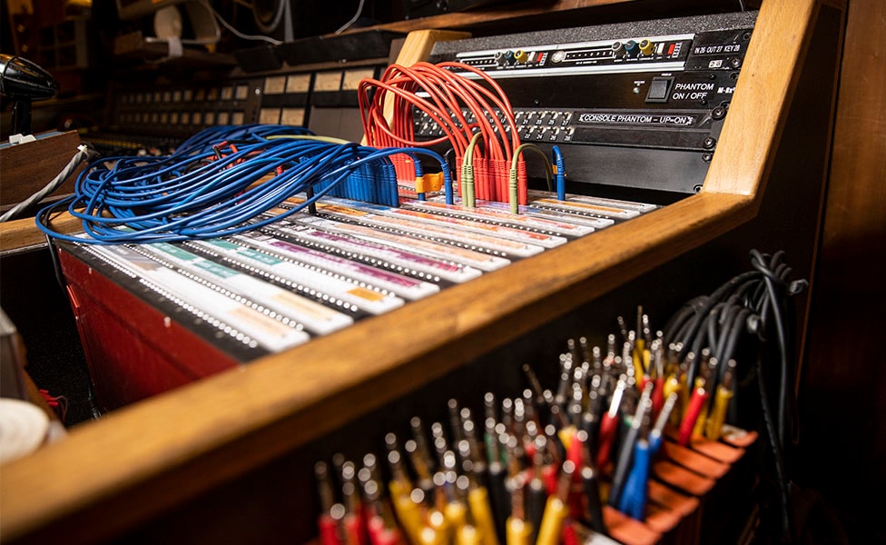
How To Set Up a Patch Bay
While it can feel like a daunting task to set up your patch bay for the first time, a solid understanding of how a patch bay works can simplify the process. The most conventional setup involves connecting the analog outputs from your gear to a bank of patch points on the top row of your patch bay, and the analog inputs to the bottom row. For a simple way to get started, you can work your way down the signal chain, including mic/line outputs, preamp inputs, DAW returns, console inputs, AUX sends, miscellaneous outboard gear and anything else you might want to route. If you have any questions about how to use a patch bay and how it can help your workflow, contact Guitar Center Professional for free information and advice.
The Difference Between Full-Normal and Half-Normal Configurations
If you already have experience with patch bays, you have likely come across the terms full-normal and half-normal. These describe how signal flows (or doesn’t flow) between the top and bottom patch points.
Normal (Full-Normal)
When a patch bay is configured as “normal” or “full-normal,” the signal is automatically routed from the top row to the corresponding channel on the bottom row. This is most common for making preamp connections, in part because you don’t have to worry about accidentally plugging or unplugging a cable that might disrupt phantom power and damage your microphone.
Half-Normal
By design, half-normal also automatically routes signal from the top row to the bottom row, but with one important caveat. That signal routing is broken when a cable is inserted into the bottom (input) jack. A common routing scheme is to “mult” out a signal from the top row and send it to another device, while simultaneously routing the same signal to the corresponding channel on the bottom row—a popular technique when working with AUX sends and effects.
Non-Normal
When a patch bay is configured as non-normalled, you will need a patch cable to make a connection between any two pieces of gear. There are no automatic connections between any two patch points, so it’s a great way to protect devices from accidentally receiving unintended signals.
Many patch bays allow you to configure the type of normalling on a per-channel basis. This level of flexibility is great to have whether you’re integrating your first patch bay or already have a setup with complex routing requirements.
Planning For Your Patch Bay Integration
As we mentioned earlier, the better you plan ahead, the easier it will be to set up your patch bay. Here are some simple tips to help you get organized before you start running cables:
- Take a full inventory of every piece of gear in your studio, including its location
- Document all inputs and outputs separately for each piece of gear
- Identify the connection types for each piece of gear, whether XLR, TRS, AES, etc.
- Measure and confirm the distance to each piece of gear from the patch bay location
- Be sure to include some slack so that you have some room to work with the cabling during install and in the future
- And don’t forget to budget for quality patch cables, whether they are TT, TRS or XLR
Speak to a team of experts at Guitar Center Professional to develop a personalized patch bay integration plan.
Signal Flow Suggestions
While every studio is different and requires a tailored patch bay layout, there are some aspects of patch bay signal flow that are nearly universal. Here are some best practices to get you started as you map out your studio signal flow diagram.
Signal Routing
As we mentioned earlier, a typical patch bay layout has outputs on the top row, and inputs on the bottom row. Depending on your audio interface and its capabilities, you may require between 8 and 16 interface inputs and outputs, 4 to 8 inputs and outputs for external mic pres, and a host of additional connections for any outboard gear I/O. Document all your I/O needs and triple check your math. For expert advice that’s customized based on your signal routing needs, contact your local Guitar Center Professional for a free consultation.
Wiring Tips
Since you already have an understanding of how normalling works, you can now make informed decisions on which channels should be full-normalled or half-normalled. If you anticipate a connection is rarely going to change, like mic lines to mic pre inputs (or mic pre outputs to interface line inputs), those are perfect candidates to set to full-normalled. If, on the other hand, you intend to mult certain connections (like insert returns and multi-track returns), you’ll likely prefer to configure those channels as half-normalled for better flexibility.
Grounding Considerations
Often overlooked during planning, proper grounding of your patch bay is paramount to avoiding issues with noise and ensuring the cleanest audio performance possible. There are four main grounding schemes, and many patch bays allow you to configure them to your preference.
An isolated ground configuration has each patch point isolated from the front panel and the other jacks. Each jack has its own independent ground and terminates in the back of the unit. An isolated ground scheme is a good choice if you have gear that is known to create grounding issues, though it can present some challenges if you intend to run phantom power through your patch bay.
A bussed ground configuration is a grounding scheme in which all of the patch points are “bussed” together to form a common ground. The common ground is then terminated at a post on the back of the patch bay. A bussed ground setup for your patch bay is a great choice when you are confident that your studio has a flawless electrical grounding scheme.
A looped ground combines each top row patch point and its corresponding bottom row patch point so that they share a common ground, but are isolated from the other vertical pairs of jacks. This can be a good configuration when you need to connect the shield from an audio source (top row) to the normalled destination (bottom row). The most common real-world application for a looped ground scheme is when you need to pass phantom power over normalled patch bay connections.
A switched ground is practically identical to a looped ground configuration, but when you insert a cable into one of the patch points, you lift the shield.
Grounding considerations are one of the most important aspects of your patch bay installation. Contact Guitar Center Professional for expert advice on how to choose the best grounding scheme for your studio.
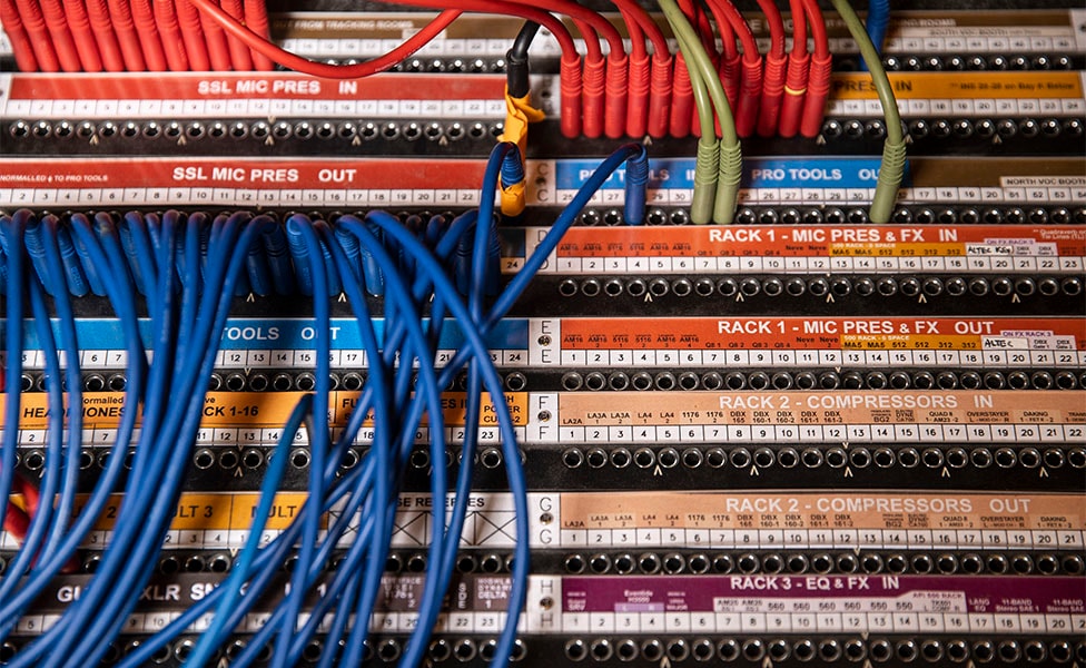
Labeling Tips
Many patch bay manufacturers offer templates and patch bay diagrams so you can easily label the patch points on your new patch bay. If you’re unsure how to organize the order of your jacks, it’s common to start with mic lines from your live room at the top, with mic pre inputs underneath; followed by interface outputs on the top and interface inputs on the bottom. Then simply work your way through the rest of your gear, with outputs being on the top row, and inputs on the bottom.
Patch Bay Recap
When deciding on the patch bay that’s right for you, remember to consider a few key factors:
- Take a full accounting of all your gear and its inputs and outputs
- Identify the types of connectors you’ll require
- Make sure your patch bay is flexible enough to accommodate your signal flow requirements
- Confirm that you have normalling options if you need them
- Plan and measure your cable runs so that you can be successful out of the gate
- Determine the best grounding scheme for your studio’s setup
Contact Guitar Center Professional to speak to a team of studio experts for a free consultation. They’ll help you find the perfect gear for your studio and make sure everything gets set up correctly with our white glove delivery and installation service.